Robot Path Planning
A critical component of autonomous robotic systems is robotic path planning, which focuses on finding the best route for a robot to take from its current position to a predetermined destination while avoiding obstructions and obeying particular guidelines. It is essential to improve the operational effectiveness and safety of robots in dynamic situations, which is why in this section we investigate several existing literature and summarize their work.
Explore Locally, Plan Globally: A Path Planning Framework for Autonomous Robotic Exploration in Subterranean Environments [1]
A multitude of works exists for autonomous exploration in uncharted environments one of peculiar interest being by [1]. In their work a path planning framework for autonomous robotic exploration in subterranean environments such as underground drifts using RRT* algorithm and graph-based Search. Their proposed solution uses a two-stage path planning architect to empower rapid exploration along very long underground drift and the ability to appropriately handle multi-branching topologies being a local exploration layer and a global exploration layer. In this exploration planner architecture, If the local planner layer reaches a dead end or any other situation that prevents the derivation of an effective exploration path, Global Planner is activated. Global Planner then has two choices either relocate the robot to a frontier of exploration or guide it back to its home location. For the case of Underground mine exploration, the local planner normally makes sure that the robot maintains exploring effectively over mine drifts, while the global planner repositions the system to recently visited and multi-branching junctions. The diagram for the proposed path planning solution is given in Fig. path_Planning.webp
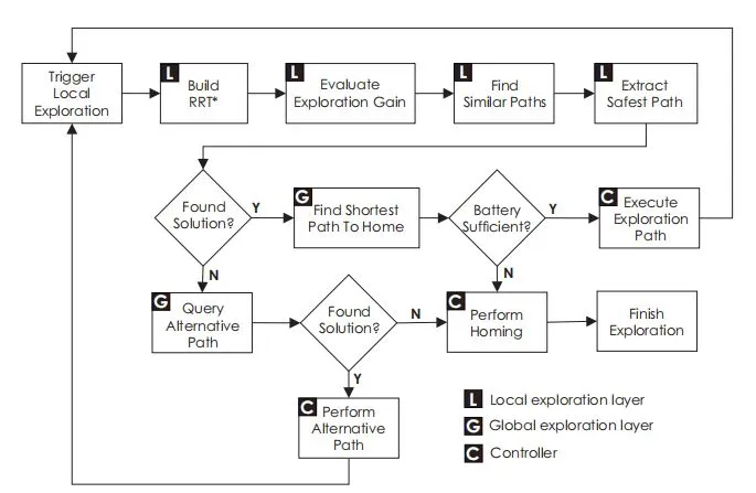
In the local exploration layer, the front end of the proposed architecture. At its core RRT* Algorithm is used to build the first random tree. To achieve rapid exploration RRT* algorithm is being used in the proposed strategy because it provides collision-free and minimum-length paths. After the generation of the collision-free paths Planner then identifies the branch with the highest exploration gain given the currently acquired occupancy map. The dynamic time warping method (DTW) was utilized to calculate the similarity between paths for time series signals [24]. To provide reliable autonomy, navigating in the confined and tiny tunnels of subterranean environments demands additional safety considerations. In order to achieve the goal, the planner considers the distance between each node and its closest obstacles in the occupancy map and determines the best exploration route that maximizes the robot’s clearance from obstacles while maintaining high exploration gain. The entire process is repeated until there is no exploration path remaining or the Platform’s low battery threshold is reached. Three use cases were tested by the author, one in simulation and two in real-world. In the first use case for simulation, the test has been conducted on a 1.4km long simulation environment created in the Rotor S simulator with ROS-Gazebo [25]. It is modeled after typical underground mines with numerous long, narrow corridors, crossings, and cycles. For use-case two, a series of robotic field deployments were carried out at the ”Lucerne” underground mine in Northern Nevada to illustrate the suggested path planning algorithm’s practical use and to comprehensively assess the algorithm’s effectiveness. The proposed algorithm was evaluated using an aerial robot based on the DJI Matrice M100 quadrotor. A Velodyne PuckLITE LiDAR unit with a maximum range of 100 meters and fields of view of FH = 360 degrees and FV = 30 degrees was installed on the robot. An Intel NUC-i7 (NUC7i7BNH) computer integrated into the robot performs all localization, mapping, trajectory tracking control, and path planning operations in real time.
In use case one, the proposed exploration pipeline successfully explored and mapped the whole area during the experiment. For use case two, the aerial robot is launched from outside the mine portal entrance in order to evaluate the application of the suggested path planning algorithm to autonomously explore an underground mine. The robot safely returned to its takeoff place after entering the main mine drifting autonomously and continuing the volumetric exploration of the underground structure until its battery allowance was consumed. In use case three, by commencing the exploration from within the sub-tunnel, he primary mine drift offered two diverging paths for the robot to consider. Upon reaching the initial junction, the robot opted for the left path, systematically exploring it by evaluating the anticipated gain in volumetric exploration.
The Strategy and techniques proposed in this paper can have a major role in our thesis contribution as it gives the solution for very large-scale multi-branched subterranean environments. RRT* algorithm along with the graph-based search method will be required for path planning in tunnel inspection. The diagram path_Planning.webp for the path planning solution has a lot of similarities to our case.
LAMP 2.0: A Robust Multi-Robot SLAM System for Operation in Challenging Large-Scale Underground Environments [2]
The contribution of LAMP 2.0 comes from [2]. The work they have done showcases a multi-robot slam system developed by incorporating a single robot adjustable with different odometry and lidar sources. An expandable multi-robot front-end with loop closure detection for large-scale environments and multi-robot teams, and a robust back-end equipped with pose graph optimization. This leads to the solution of multi-robot exploration in challenging conditions.
The proposed solution includes a single-robot front-end interface for robots, receiving odometry and point cloud streams, and sending pose graph segments to a centralized base station. A multi-robot front- end maps the area and detects multi-robot loop closures. A multi-robot back-end optimizes trajectories using odometry and loop closures from all robots for joint pose graph optimization. An overview of the proposed architecture is shown in Fig 205f1.webp
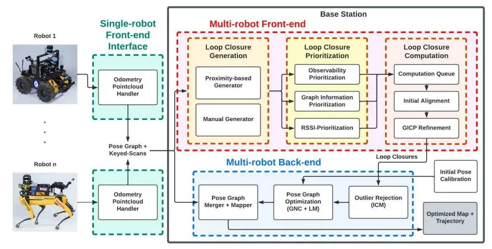
and lidar setups. Pre-processing is done before the front-end interface is created. The Heterogeneous Robust Odometry (HeRO) [26] system corrects distortions in lidar scans caused by the robot’s mobility. Undistorted point clouds are combined into a single point cloud using extrinsic calibration between lidar scanners. An adaptive voxelization filter removes redundant and noisy points from the unified point cloud, ensuring the same number of points regardless of the environment geometry, point cloud density, or the number of onboard lidar scanners [27]. LAMP uses a pose graph formulation [28] to represent the estimated robot trajectory, with each node representing an estimated pose and each edge representing relative motion or position measurement between nodes.
The proposed SLAM architecture uses a multi-robot front-end for detecting intra- and inter-robot loop closure. The loop closure detection module involves the creation, prioritization, and computing steps. Feature-rich regions are prioritized in the generation phase, while graph information prioritizes loop closures if they significantly reduce trajectory error. A Graph Neural Network (GNN) [29] is used for pose graph optimization, while the Receiver Signal Strength Indication (RSSI) Prioritization module prioritizes loop closures based on known locations. A two-stage pipeline is implemented for each loop closure candidate, starting with an initial alignment for the relative transform estimate using TEASER++ [30] or SAmple Consensus Initial Alignment (SAC-IA) [31], and then using the Generalized Iterative Closest Point (GICP) [32] algorithm to obtain the refined relative transform.
The study tested the use of LAMP 2.0 using two robot types: Husky and Spot. Husky has three Velodyne lidars and a Hovermap [33], while Spot has either a single lidar or a hovermap. LAMP 2.0 receives odometry information from either the Hovermap [33] or LOCUS [27]. The foundation was a mobile workstation with a 64-core AMD Ryzen Threadripper 3990x CPU and an Intel i7-8750H laptop with 12 cores. Four datasets were used to evaluate LAMP 2.0: the Tunnel Dataset, the Urban Dataset, the Finals Dataset, and the Kentucky Underground Dataset.
Robot Navigation
Integrated together, robotic mapping and navigation enable intelligent mobility in a variety of settings, making them essential components of autonomous robotic systems. The task of navigation involves organizing and carrying out a robot’s travel from its current location to a predetermined destination while making decisions based on sensor inputs. Robots are able to traverse and adapt to changing surroundings with the help of path-planning algorithms, which are essential for navigation. These algorithms optimize paths depending on variables including distance, time, and safety due to which we explore different academic works pertaining to navigation and mapping.
Autonomous Mapping and Exploration with Unmanned Aerial Vehicles Using Low Cost Sensors [34]
The framework for Autonomous Mapping and Exploration with Unmanned Aerial Vehicles Using Low-Cost Sensors is presented by [34]. Their work represents exploration in fully unfamiliar environments with low-cost sensors such as LIDAR and RGBD cameras through UAVs.
It solves the issue of autonomous mapping and exploration in such environments where no prior information is available about the environment [35], [36]. Also, it solves the issue of exploration where GPS is not available and UAV has to be dependent only on onboard sensors for localization and navigation. In the view of the writer [34] ”there are many techniques available mainly for ground robots including multi-robot systems [37], [38]. There are many SLAM techniques that have been successfully employed in the past that use various sensors and combine the data to provide informed decisions about the environment [39], [40], [41], [28], [42]”
Their proposed solution employed a frontier-based exploration strategy to maximize the map’s coverage. They used an extended Kalman filter to combine all the sensor data from the UAV, creating a unified navigation system that controlled the UAV’s velocity, orientation, and position while accounting for sensor error bias. A set of PID controllers was applied to control the attitude, yaw rate, and velocity of the UAV as well as the heading. The use of arduPilot to translate output messages (Values that contain thrust and torque) into motor voltages in contemplation of simulation and flying the vehicle [43]. For mapping, the Author used GMapping or grid mapping to build a 2D occupancy grid map (also utilized for frontier exploration) from LIDAR and pose data from UAV. The GMapping method utilizes a Rao-Blackwellized particle filter which re-samples each particle in a repetitive way, dropping the bad particles while making sure to keep the good particles. To approximate the pose of the vehicle with consecutive laser scans, a laser scan matching algorithm was used. To rebuild a dense 3D map of the environment the 3D point cloud produced from the Kinect sensor was also stored. For Exploration, the Frontier exploration method was used. The technique is based on a straightforward idea: as additional areas are examined; the boundary is pushed as a result of constant increases in new information about these frontiers [44]. Different factors, including the distance to the frontier from the present position and the size of the frontier, were used to determine which frontier is the ideal one to visit next. The grip map was updated using the SLAM approach as the UAV continuously explores the area and is used for autonomous navigation.
To autonomously navigate from one point to another in the grid map the navigation planner utilizes the local and global planner.
Global Planner: Uses A* algorithm to plan the route from the current pose to the goal pose.
2. Local Planner: Calculates the linear and angular velocities using the dynamic window approach (DWA) [45] along the global path while avoiding static or dynamic obstacles based on the cost map parameters.
To correct the position of the UAV a scan matcher node coincides with the laser scans with respect to the map. The adaptive Monte Carlo localization (AMCL) stack, which is accessible on ROS, was used for the localization. By comparing the laser scan data from the robot in a specific pose with the map, localization was accomplished. A quick image matching methodology was used to apply a loop closure detection method by collecting reliable characteristics from the image (e.g., scale-invariant feature transform (SIFT) or Speeded Robust Features (SURF) ). Matching and stitching the 3D data acquired from the RGBD camera is done using the iterative closest point (ICP) method (3D variation). The produced point cloud was sent to the ROS module OctoMap, which turns it into a 3D occupancy grid map. OctoMap divides the point cloud recursively into octree cells that are further divided into occupied and unoccupied cells using an octree data structure.
For the testing of the use case, The simulation model was based on the Asctec Hummingbird multirotor and is equipped with a Microsoft Kinect that serves as an RGBD camera and an Inertial Measurement Unit (IMU) for a 9 DOF position estimation and a 2D Light Detection and Ranging LIDAR sensor. Testing revealed that this setup, with the Kinect sensor positioned on top, offers improved agility. For Programming and control, ROS was used. To test the Proposed algorithms, an interior environment was built and a simulation model of the drone was created in the Gazebo simulator.
The author states “From the results, we confirm that autonomous operation using only an RGBD camera is possible for the UAV system” “The UAV was able to explore all the areas successfully using frontier exploration” [34]. A detailed 3D map of the inside environment was created using the RGBD camera’s data. Spatial alignment does this by geometrically aligning a set of photographs taken at various times from the same scene using different sensors or different view-frames.
RGBD camera can be used in our thesis with the uncertainty that the tunnel environment can be completely dark or might be with bad lighting conditions. While RGBD cameras are designed to work in various lighting conditions, their performance in dark or low-light environments can be limited. A* algorithm can be required in our case. Ardupilot and Octomap can also be utilized for control of the robot and generation of a 3D occupancy grid Map.
Framework for UAV Navigation and Exploration in GPS-denied Environments [3]
For the purpose of Exploration in GPS-denied Environments a Framework for UAV Navigation is proposed by [3]. Their work demonstrates the creation of a framework that makes UAVs capable of navigating in mysterious, unshaped, and GPS-blocked Environments such as inside mines, building basements, etc. as a sequential decision process under uncertainty using POMDP. It solves the issue of robotic navigation and exploration in environments like natural or urban canyons or dense canopies where GPS signal access is not possible. The writer’s work is the extension of research work by [46], [47] in which the author has developed a system for UAV Uncertainty-Based Navigation (UBNAV) using POMDP.
In their proposed solution they have utilized Localization algorithms (e.g. SLAM [48], [49]) and/or Visual odometry (VO) [50], [51] with POMDP [52], [53]combined into a framework in order to model the sequential decision problems in navigation and exploration tasks. The ambiguity caused by the motion model and the unavailability of GPS of UAV is dealt with POMDP which provides a motion plan for UAV navigation. In order to plan a sequence of motion commands the POMDP planner requires an occupancy map which can be generated using the octomap library [54]. These motion commands are forwarded/redirected to the UAV flight controller using mavlink through mavros messages. In POMDP the state of the process is characterized by a probability distribution over possible states and it is called the belief state.
The author [3] used TAPIR [55] software to navigate and explore the sequential decision problem of the UAV, utilizing ABT(Adaptive Belief Tree) [56]. The occupancy map is updated with new data collected by a depth sensor. The POMDP formulation models modifications in the map and unrecognized places. The state variables (S) include the position and heading angle of the quad-rotor, forward and lateral velocity, and obstacle detection variable ob in front. The author assumes minimal wind conditions and the UAV is 1m above the ground, neglecting ground impacts.
The set of actions in the POMDP formulation are motion commands for four state variables, with the PID controller controlling each variable. The environment is recognized by two variables: onboard estimated pose measured in the local frame and a second boolean variable ob. The transition function models the dynamic response to motion commands, while the 3D occupancy library models the environment map. The mission objectives are modeled using the reward function. Fig. 128fig1.webp shows the implementation of the framework proposed by the author [3] in simulation.
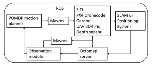
The author [3] tested the framework in simulation using software in the loop (SITL) and used a model of an off-the-shelf UAV(3D iris) flying in different simulated worlds with a mission to explore the environment and generate an occupancy map along with avoiding obstacles within operational air space. For the first scenario, UAV has to take off in front of the collapsed building with a prior map generated based on a point cloud by depth sensor with the view in front of the UAV. In the second scenario, the UAV needs to produce a map of the space under the gas station ceiling while navigating safely. In this scenario, the UAV pose will come from SLAM.
The result for the first scenario shows that the UAV successfully explores the environment and creates and updates the map while avoiding obstacles. In the second scenario, as the UAV enters the GPS-denied zone, it performs actions to maximize the information gain while keeping a safe distance from the walls. In our thesis, one of the major problems which we have to tackle is the absence of GPS. Their work has presented a valuable framework for exploration and navigation in GPS-denied environments. It can have a significant contribution to our thesis.
Robotic Simultaneous Localization and Mapping
An important advancement in robotics is called simultaneous localization and mapping (SLAM), which enables a robot to map its surroundings in real time and identify its location on the map. Because it allows for efficient navigation and decision-making, this dual feature is essential for autonomous systems working in unfamiliar or dynamic situations. We analyze a variety of research papers to query state-of-the-art techniques that may be utilized in our work.
Rhino: An Autonomous Robot for Mapping Underground Mine Environments [4] An Autonomous Robot for Mapping Underground Mine Environments put forward by [4] Their work demonstrates RHINO, an autonomous robot that navigates underground mines using LIDAR and IMU and generates 3D maps using the LIO-SAM framework. It addresses the issue of the robots navigating in underground mines while the underground mines are GPS-denied environments where robots can not be dependent on satellite-based navigation in order to update their state estimation during the mission. Also, the terrain in an underground mine can be rugged due to large rocks and mud. The writer claims that ”solutions that were developed for underground mines include CompSLAM [57], Wildcat SLAM [58], LOCUS/LAMP [59]and LIO-SAM [60].”
For the proposed solution the Software architecture is divided into four parts: Hardware interface, State estimation, Planning, and User interface. The overview of software architecture is shown in Fig. 203fig1.webp . In the hardware interface module, software is developed to communicate with onboard sensors

and electronics. The robot serves as the router server and the base station serves as the client so that continuous operation can be maintained even when the connection to the base is lost. The state estimation module ensures accurate localization of the robot during autonomous navigation tasks. It uses the LiDAR-inertial odometry via smoothing and mapping (LIO-SAM) SLAM framework [60], which supports global optimization and multisensor input. The Allan Variance approach [61] and complementary filter [62] calibrate IMU data before estimating orientation estimates. The planning module receives waypoint commands and transmits velocity orders back to the robot. It includes modules for path-following, local planning, and terrain analysis.
The terrain analysis creates a 15m by 15m terrain map, while the local planner algorithm receives inputs from the terrain map and waypoint goal. The Monte-Carlo method samples the robot’s motion primitives. The path follower algorithm generates a velocity command for the motor controller at 20Hz using the odometry and goal path. A graphical user interface is created to provide user feedback on the robot’s performance. Goals can be established through the user interface or autonomous decision-making algorithms, such as task planners or exploration algorithms. For the use case, the primary restriction was the battery’s weight to enable the robot to continuously operate for more than 6 hours. The wheel design was chosen with a split-body chassis because it allows all four 0.5m wheels. Ten 12.8V Lithium Iron Phosphate (LiFePO4) batteries were chosen with a combined energy of 420Ah and a combined weight of 58kg.
The robot’s localization, waypoint navigation, and obstacle avoidance capabilities were evaluated on various surfaces, including an outdoor gravel landscape, an indoor obstacle course, and an underground mine. The robot was deployed using a base station and monitored using a user interface. Tests were conducted on a gravel landscape, where user-generated waypoints were used for navigation. An indoor obstacle course was constructed using cardboard boxes, assessing the robot’s ability to weave past obstacles and navigate through maze-like patterns. The robot’s ability to work in underground conditions was verified during trips to the National Institute for Occupational Safety and Health Coal Mine in Pittsburgh. A set of free valid waypoints was constructed based on a previously created map using teleoperation, allowing the robot to navigate the waypoints in order.
The robot, named Rhino, completed several tests, showcasing its ability to navigate autonomously and avoid obstacles. During Test 1, Rhino could cover 3.6 kilometres in 150 minutes. In Test 2, the robot could navigate obstacle courses and drive for over 6 hours on a single battery cycle. In the Underground Mine case, Rhino navigated various terrains, including gravel, dry, and muddy surfaces, while maintaining its state estimation. However, the operators chose not to traverse the mine’s areas due to water levels. In the Waypoint case, the robot switched to waypoint driving mode without restarting the system, allowing it to use the previously generated localization solution. The experiments confirmed Rhino’s ability to follow the planned path autonomously and achieve its goals.
The development of Rhino and its application to autonomously operate in underground harsh environ- ments is similar to our case. The proposed electronic hardware with 6 hours of battery backup can be quite valuable in our thesis as it may require long missions if the tunnel is extensive.
Targetless Camera-LiDAR Calibration in Unstructured Environments [5]
The work for Targetless Camera-LiDAR Calibration in Unstructured Environments is exhibited by [5]. Their work presents a unique adjustment method in order to achieve six degrees of freedom (6-DOF) rigid body transformation estimation (as known as extrinsic parameters) between the camera and lidar sensors without any need for an artificial target or a structured environment. It solves the issues of camera-lidar calibration in the unstructured environment without any artificial target provided.
The writer [5] contends that ”a large number of camera-LiDAR extrinsic calibration works are target- based. With this methodology, a known artificial target is used to be detected by both sensors. In [63],- [64], the authors use a chessboard as a target. Planar marks are also used in [65], Other types of marks with different geometric shapes are also often used, such as spheres [66], triangles [67] or polygons [68], [69]. Motion-based calibration methods estimate odometry with each sensor separately, and simultaneously estimate extrinsic parameters that minimize the error between calculated paths [70],[71]. There are other different works in this line focused on improving the arrangement of the edges [72],[73].”
The proposed solution comprises of novel co-registration approach that utilizes local edge features in an inconsistent environment to acquire 2D to 3D errors between the data of both the camera and lidar. After obtaining 3D to 2D errors, the relative transform(i.e. the extrinsic parameters) is predicted in order to minimize these errors. To find the best transform perspective-three-point (P3P) algorithm is used. A Kalman Filter was employed, which gave the system excellent stability against noise disturbances, to further clarify the final calibration. The suggested calibration procedure was broken down into three steps. In the first step, it pre-processed each sensor’s input and projected the LIDAR points into the image plane. After receiving the data that has been processed, the second step co-registers the LIDAR feature points with the points from the image’s features to produce the 3D-to-2D matches and their errors. In the third step, it used the PnP-based P3P method to estimate extrinsic parameters and the RANSAC variant MSAC to detect inliers. An overview of the process explained is shown in Fig. 11fig1.webp
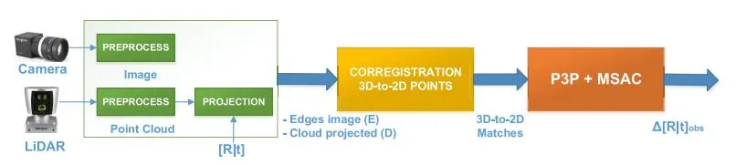
For the part of sensor data pre-processing it is necessary to figure out the edge intensity value for each pixel in each camera image (I). Outdoors, it’s common to find spots with intense lighting, which makes other parts of the same image heavily shadowed and lose the edge definition. In the initial stage of picture pre-processing, histogram equalization was performed on I to enhance the contrast of shaded areas. The edges of the objects could not line up exactly since LIDAR and camera sensors can detect objects from various angles. Due to this, a Gaussian filter was used to broaden the borders of the equalized image, effectively smoothing the objective function to maximize edge alignment. In the Co-Registration of Camera-Lidar points, the author clustered at D points, first in the depth dimension and then in the two dimensions of the picture plane, to perform edge alignment at the object level. In 3D-to-2D relative transform estimation, Reprojection errors were defined by the pixel spacing between the points. Then estimation of extrinsic parameters minimized the errors. For the best solution P3P algorithm based on Pnp was utilized, It required a minimum of three inliers to perform the estimation. A variant of RANSAC (MSAC) was used to detect inliers in estimation.
For the testing of the use cases the quantitative outcomes were acquired by applying the strategy to various types of environments derived from the Kitti dataset [71], utilizing the calibration provided by this dataset as ground truth. The author used a ”training” set D made up of 560 samples of camera-LiDAR data from the Kitty dataset as well as the calibration of the dataset offered as ground truth to simulate the observation noise for the tests. In the noise model for the Kalman filter, the graphs were created by processing 5,600 frames and determining the inlier percentage and inaccuracy relative to the ground truth for each batch of 10 frames.
Results from experiments were a comparison of the proposed method to others. It was observed that compared to other methods, the proposed strategy greatly improves the outcomes. The proposed approach improved standard deviation precision. It also has the benefit of being online and applies to applications requiring autonomous navigation.
The result of the proposed method is a comparison based so it is still unclear how it can be utilized in our use case. Since the method proposed by [5] is online unlike others it can be used for autonomous navigation.
Robotic Exploration
Robotic systems are becoming essential for navigating and exploring regions that are dangerous or difficult for humans to reach in the field of underground exploration. Tunnel exploration, mining activities, and subterranean infrastructure maintenance are examples of targeted uses. Robots with sophisticated sensors and navigation systems that are deployed in tunnels do inspections, evaluate the structural integrity of the tunnel, and detect potential risks, all of which increase productivity and safety while dealing with tunnel-related duties. Self-navigating robotic vehicles in mining operations traverse tunnels to harvest resources and investigate mineral deposits, hence improving subterranean operations’ efficiency. In this section, we investigate existing exploration techniques from prior works.
Exploration-RRT: A multi-objective Path Planning and Exploration Framework for Unknown and Unstructured Environments [6]
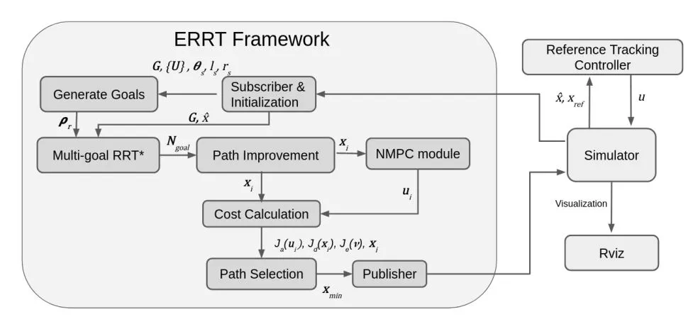
Another framework for multi-objective Path Planning and Exploration for Unknown and Unstructured Environments is presented by [6]. In their work, the Exploration-RRT (ERRT) system has been developed mainly for use in 3D exploration missions in partially or entirely unknown and unstructured terrain based on multi-goal Rapidly-Exploring Random Trees(RRT). It solves the issues for robots where robots are given the responsibility of exploring and identifying artifacts in challenging, unstructured environments.
Their solution for the combined path planning and exploration problem is approached by formulating a minimum cost problem. This involves using pseudo-randomly generated goals and combining them with multi-path planning and evaluation. To the best of the authors’ knowledge [6], no previous methodology has ever included the model-based actuation, based on a nonlinear system model along each generated trajectory, along with the information gain and the overall distance. Moreover, ERRT takes into account the entirety of the unknown map, provided that there are feasible frontiers or sites of interest. An overview of the exploration-RRT framework and pipeline(left) and simulation architecture(right) is shown in Fig. 98fig1.webp
The proposed method was evaluated in simulated scenarios, considering a non-linear dynamic model of a UAV with added minor localization noise and a sensor model that required a voxel to be 1 m closer to be considered discovered compared to the ERRT. The whole space was initially marked as unexplored on the map, with the exception of a tiny region immediately surrounding the starting point. As each voxel’s center enters the sensor range, it is either marked as free space or as occupied. The result of their work was a fast-based exploration strategy. However, a benchmark was not performed with other existing strategies.
The use of ERRT can have an effective contribution to our thesis as it is designed for utilization in 3D exploration missions in partially or completely unknown and unstructured environments same as our case. Moreover, RRT* will be useful as it can carefully investigate the area and produce pathways that avoid obstacles in an environment where the obstacles and structure are unknown in advance.
Experimental Evaluation of Some Exploration Strategies for Mobile Robots [23]
Very few works of experimental evaluation of exploration strategies are available. One of them is presented by [23]. Their work presents an experimental evaluation of different exploration strategies in order to obtain their advantages and disadvantages by implementing them in 3 different environments in simulation. The proposed solution involves using a mobile robot equipped with a sensor to explore an unknown environment. The procedure involves creating a local map showing the area of the environment, updating the global map, and applying the exploration approach to determine the next observation site. Maps are constructed incrementally by integrating measurements based on the robot’s estimated positions [74] or the geometrical characteristics of the maps [75], [76]. The exploration strategies experimentally compared include random, greedy, GB-L, and A-C-G strategies.
For testing of the use cases, a software simulator was used which uses LEDA libraries for data structures and graphics and C++. Three different environments have been used to evaluate the exploration strategies. The first one is an office-like setting (office environment), which has three corridors. The second (open environment) is a large open space, similar to a large outdoor area. The third one is a large space area filled with various obstacles.
The simulations were evaluated for the office, open, and obstacle environments. From the results, it was clear that in all situations, exploration proceeds more quickly the wider the sensor’s range and more slowly the larger the C. There isn’t a lot of difference in the strategies when the number of steps are taken into account. This is caused by the fact that for all methods, the candidate observation places are created along the free edges. In both large environments, the greedy strategy appears to perform worse than the GB-L and A-C-G strategies, suggesting that adding a cost while computing f(.) can have some benefits. The A-C-G approach seems to perform better than the GBL method in open environments, but the two are nearly equal in situations with obstacles (A-C-G performs slightly better in terms of steps taken, while GB-L performs better in terms of distance traveled).
As seen in the results A-C-G and GBL strategy both performs better in environments with obstacles considering the fact that they are evaluated in only simulation environment. Any of them will be selected if needed in our case.
Autonomous Search for Underground Mine Rescue Using Aerial Robots [8]
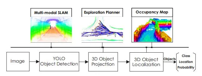
The work for Autonomous Search of Underground Mine Rescue Using Aerial Robots is the contribution of [8]. Their work presents a comprehensive solution for autonomous underground mine exploration with the ability to localize and map in subterranean settings and also identify and localize objects of interest for the purpose of mine rescue. This is achieved by combining lidar data with thermal vision frames and inertial cues.
In their proposed solution the airborne robotic platform is outfitted with a) a strong localization and mapping system to gradually develop the map of the environment, b) a path planning algorithm to support quick exploration, c) a convolutional neural network (CNN) to identify probable items from color image frames, and d) a Bayesian updating approach to determine the related 3D coordinates of those objects. An implementation of a graph-based bifurcated global-local strategy was made [9] [77]. In addition, a CNN model was utilized on color RGB photos to conduct object identification, together with a Bayesian filter to accurately predict the 3D position of an object in the map. An overview of the proposed approach is shown in Fig. 204f1.webp
The system was tested in an underground mine using an aerial robot equipped with an inertial measurement unit, a LiDAR sensor, a visible light camera, and a thermal camera [78] [79] to assess its resilience in sensing-degraded settings.
In the test case, the robot was able to go continuously through the 120-meter-long tunnel while accurately detecting and localizing each of the five objects in the scene with a high degree of confidence. It’s crucial to note that the objects in this particular area have never been recorded in training data and that the low lighting conditions of the test environment resulted in relatively dark photos. However, the suggested method, which made use of a tailored YOLO detector model improved by the 3D object localization technique, consistently reported all objects and was error-free.
As the application of the proposed problem is in the Underground mine having a dark environment and also the absence of GPS, it is quite similar to our case except detection of artifacts. The approach can be utilized in our thesis solution.
Autonomous Frontier Based Exploration for Mobile Robots [80]
The solution for frontier-based exploration is given by [80]. It is used for autonomous exploration of unknown environments based on frontier exploration without any map. It solves the issues of autonomous exploration where no information or map of the environment is available.
In the proposed solution Gmapping package is used for environment exploration. 2D occupancy grid maps are generated incrementally and in real-time from the laser and pose data provided by the mobile robot during its motion. move base package is used for the navigation of mobile robots in order to move towards the goal point.
The article [80] demonstrates the use of two exploration packages in order to create a map of the environment. Both of the algorithms will be considered and utilized in our thesis implementation as in our case we are required to map the environment. Furthermore, in our case, the environment is also unknown to the robot.
Towards Fully Automated Tunnel Inspection: A Survey and Future Trends [81]
The work presented by [81] discusses the present patterns in Automatic tunnel inspection and presents novel technologies including scenario modeling, robotic platforms, image and ultrasound sensors, control algorithms, and decision-making strategies. It solves the challenges of time-consuming manual inspections, ensures better quality control, enhances safety, reduces the need for extensive expertise, and provides potential cost savings in tunnel maintenance and inspection processes. According to author’s [81] perspective “the use of robotics systems in the construction field had been a common research area, and several studies review the advantages in the use of robotic platforms for construction [82] [83] and underground construction [84]purposes.”
Inspections are done to determine whether or not a structure that has been in use for a while is still secure. Non-destructive inspection (NDI) procedures [85] [86]are far more frequently utilized than destructive methods since it is also important to do this without having a detrimental impact on the structure or component. There are several different NDI techniques for structures, including visual, strength-based, sonic, ultrasonic, magnetic, electrical, thermography, radar, radiography, and endoscopic techniques. Visual methods: Distinguishing between different signs of distress that engineers may encounter is of particular importance as visual features can provide insights into workmanship, structural serviceability, and material deterioration. Strength-Based Methods: Rebound and penetration tests determine the hardness of a material’s surface and estimate the uniformity, quality, and strength of the structure as well as the surface compressive strength.
Sonic and Ultrasonic Methods: Hammer blows generate impulses in sonic procedures, commonly referred to as impact-echo tests, and the time of flight of these impulses is determined by pickups mounted on the wall [87] [88]. The strength and, thus, the modulus of elasticity, are correlated with the period of transit. The typical method for using ultrasonic devices is to measure the velocity of a pulse produced by a piezoelectric transducer within the material [89] [90] [91]. Magnetic Methods: Since corrosion-induced deterioration is frequently linked to inadequate cover, a method for locating the reinforcing bars may be crucial in corrosion control. Magnetic methods are used to locate reinforcements; they are not techniques for directly detecting defects or deterioration. Electrical Methods: Resistance and potential measurements are two electrical techniques for inspecting tunnel components [92] [93] [94] [95]. Thermography Methods: The thermal radiation that the tunnel walls release is measured by infrared thermography. The temperature distribution on the surface can be visually presented using infrared registration techniques [96] [97] [98]. Radar Methods: It is based on how electromagnetic radiation spreads through materials with various dielectric constants. Radiography Methods: The ability of X-rays, gamma radiation, and neutron rays to penetrate structural materials makes them useful for inspection reasons [99] [100] [101]. Endoscopy Methods: Endoscopes or video scopes are rigid or flexible viewing tubes that can be put into boreholes that have already been bored into an element to be studied to assess its condition [102] [103].
TunConstruct system: A robotic arm at the end of a crane that is installed on a moving vehicle makes up the TunConstruct system. A user-friendly guided HMI (Human Machine Interaction) that displays a 2D camera image stream and prompts for operation procedures is used for inspection. The process was carried out automatically by the robotic system thanks to visual servoing based on the depth measurement recorded by the tool’s laser telemeter, and operation-oriented actuators were coordinated by task-specific control software.
ROBINSPECT: A mobile robot, an automated crane arm, and an industrial-grade robot manipulator made up the three components of this robotic system. Basic 1D, 2D, and 3D sensors were integrated into the subsystems to enable collision avoidance, such as laser, infrared, and ultrasound proximity and distance sensors, as well as vision cameras and SICK sensors. In addition, a unique new ultrasonic sensor was installed to measure the width and depth of cracks.
In the use case, the TunConstruct system was tested in both simulation and the real world while ROBINSPECT involved only case studies. TunConstruct system was tested successfully first in laboratory conditions and then in real, non-controlled environments in tunnels in Le ́on, Spain. While ROBINSPECT project involved case studies and evaluations using tunnel infrastructure, including the London Under- ground, road tunnels of the Egnatia Motorway, and sections of the railway tunnel of the London Post Office. The method described in [81] for the inspection of tunnels in this paper can benefit us if we move towards an application goal in our thesis end result.
Litetrature Limitations
Significant progress has been made in recent years in the use of autonomous mobile robots for tunnel exploration and inspection. The prior research described in the chosen research articles does, however, have significant limits, as does any developing topic, which opens up possibilities for advancement and more study.
Limited Adaptability to Dynamic surroundings: A number of the exploration tactics covered in research articles, like the Exploration-RRT framework [6] and those offered by [23], may not be as effective in surroundings that are changing quickly. More research is needed in the domain of mobile robots’ capacity to adapt to unanticipated impediments, changing terrain, or abrupt changes in tunnel conditions. The specified techniques could not be resilient enough to deal with unforeseen circumstances in dynamic situations, which could result in navigation failures and impaired data collecting.
Issues with Scalability in Large-Scale Tunnels: When implemented in large-scale tunnel networks, a number of the suggested approaches, such as those in the study by [1]. on investigating underground settings, may run into problems. One major problem is scaling up the exploration tactics to span large tunnel systems without sacrificing accuracy and economy. To guarantee practical application in real-world circumstances, autonomous robots’ capacity to traverse, map, and gather data in large tunnel networks must be carefully considered.
Sensor Limitations Affecting Inspection Precision: The autonomous robotic system that [104] exhibited represents a substantial leap in robotic tunnel inspection. Nonetheless, the accuracy of structural evaluations could be impacted by sensor technology constraints. The system’s capacity to identify minor structural problems and precisely evaluate the state of tunnel infrastructure may be hampered by dependence on certain sensor types or limits in their resolution. Reducing these sensor constraints is essential to improving autonomous robotic systems’ dependability for tunnel inspection applications.
Challenges with Real-time Decision Making: A number of the investigated systems, such as the autonomous robot Rhino [4] for mapping surroundings in underground mines, could run into problems with making decisions in real-time. When it comes to adjusting to changing circumstances and guaranteeing the accomplishment of an exploration or inspection task, robots’ capacity for quick and well-informed decision-making is essential. The efficacy of the robotic system in practical applications may be jeopardized by delays in decision-making, which can also affect the efficiency of data collecting.
Standardized inspection procedures are necessary to ensure that various robotic systems are comparable and interoperable in the context of tunnel inspection. However, these standards are currently lacking. Establishing universal standards or facilitating smooth collaboration across diverse autonomous robotic systems might be difficult due to the possibility that each system, as demonstrated by [105]study, has its own set of inspection criteria and techniques. Standardizing inspection processes might boost the reliability and consistency of tunnel evaluations made by autonomous robots.
Despite the fact that the research articles included in this chapter greatly advance the state of the art in robotic inspection and tunnel exploration technologies, it is crucial to acknowledge and resolve the aforementioned drawbacks. Future studies should concentrate on reducing these obstacles in order to create more resilient, flexible, and broadly applicable approaches for the creation of autonomous mobile robots that may be used for data collection, navigation, and tunnel investigation.